
 CN
CN EN
EN ES
ES RU
RU FR
FR AR
AR
Contact Us for All Your Needs
Our professional team will be online to provide you with the most suitable products for you.


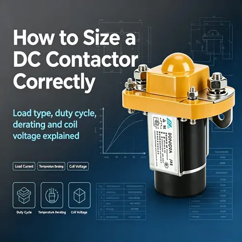
A DC contactor selected solely by matching its rated current to the load current will, in many applications, fail earlier than expected. The reason is straightforward: a contactor's ability to handle current depends on the type of load it switches, how frequently it operates, the ambient temperature at the installation site, and the coil voltage available to drive it. Each of these factors can reduce—or in some cases effectively derate—the contactor's usable current capacity. Understanding how to evaluate all four parameters together, rather than just one, leads to a contactor selection that survives the full design life of the equipment.
The starting point for sizing any switching device is the steady-state current that flows through the main contacts when the load is operating normally. This value is determined by the load power and the system voltage, and for resistive loads it is the primary number that determines the contact rating needed.
However, load type matters as much as load current. The International Electrotechnical Commission standard IEC 60947-4-1 defines utilisation categories that describe different load characteristics and their effect on contactor sizing. For a DC Contactor, three categories cover the most common applications.
DC-1 loads are non-inductive or slightly inductive, such as resistive heaters and power supply outputs. The make and break currents equal the rated operational current, and the contactor can be sized close to the steady-state value. DC-3 loads involve starting and stopping shunt motors, where the inrush current can reach 5 to 10 times the running current. The contactor's making capacity—not just its continuous current rating—must accommodate this inrush. DC-5 loads cover series motors and other heavy inductive loads where both the making and breaking currents are elevated. Selecting a contactor for DC-3 or DC-5 duty based solely on the motor's nameplate running current will result in contact welding during the first start attempt.
The utilization category for the intended load should appear in the contactor's technical documentation. If the application involves frequent motor starts or inductive load switching, specifying the correct utilisation category during selection is not optional.
The duty cycle describes how the contactor operates over time—how long it remains closed, how long it remains open, and how frequently it cycles. Contactors in continuous-duty applications, such as power supply outputs that stay energised for hours, dissipate heat steadily through the contacts and coil. The thermal equilibrium reached determines whether the contactor operates within its temperature rating.
Contactors in intermittent or frequent-start applications face a different stress. Each closing operation generates an arc that erodes contact material, and each opening under load generates an additional arc. The contactor's electrical life—the number of operations it can perform at a given current before the contacts wear beyond specification—is specified by the manufacturer for each utilisation category. For applications exceeding 100 operations per hour, the contactor should be oversized relative to the continuous current rating to account for the accelerated contact wear caused by frequent arcing.
The contactor's datasheet typically provides curves or tables showing electrical life versus switched current. Selecting a contactor that operates on the upper portion of this curve, where a small increase in current causes a large decrease in expected life, leaves no margin for load variations or ageing. A conservative selection places the operating point in the middle or lower portion of the curve.
Contactors are rated at a reference ambient temperature, commonly 40°C or 55°C depending on the standard applied. When the installation environment exceeds this reference temperature, the contactor's current-carrying capacity must be reduced. The derating factor varies by contactor design and manufacturer, but a typical rule for industrial contactors is a reduction of approximately 1% to 1.5% in rated current per degree Celsius above the reference temperature.
For an application where a contactor rated for 200A at 40°C is installed in a photovoltaic inverter enclosure where the internal ambient reaches 65°C, the derating calculation shows the usable current drops to approximately 125A to 150A depending on the specific derating factor. Installing a 200A contactor in this environment and loading it to 200A will result in overheating, accelerated contact oxidation, and eventual thermal runaway at the contact points.
The practical implication is that the installation environment must be assessed before the contactor is selected, not after. Enclosures without forced ventilation, outdoor installations in direct sunlight, and equipment cabinets with multiple heat-generating components all produce ambient temperatures significantly above the surrounding room temperature. The contactor mounted inside such an enclosure experiences the internal ambient, not the building's air-conditioned temperature.
For applications with elevated ambient temperatures or limited enclosure ventilation, reviewing DC switching component specifications across multiple current ratings can help identify a contactor with sufficient derated capacity to operate reliably in the actual installation conditions.
The coil circuit controls the contactor's mechanical operation, and coil voltage selection is equally critical to main contact rating. DC contactor coils are typically available in standard voltages including 12V, 24V, 48V, 60V, and 72V DC, with some product lines extending to higher voltages for specific applications.
The coil must be matched to the control system voltage available at the contactor location, accounting for voltage drop in the control wiring. A contactor with a 24V coil installed at the end of a long control cable run may receive only 20V to 21V at its coil terminals due to wiring voltage drop. If the contactor's minimum pull-in voltage is 70% of rated coil voltage—a typical specification for DC contactors—a 24V coil requires at least 16.8V at the terminals to close reliably. The 20V to 21V example leaves margin, but as the control transformer ages or if the cable run is extended during maintenance, that margin can erode.
The coil's power consumption also affects the control system design. Coil power ratings commonly range from 8W to 15W for medium-current DC contactors. In battery-powered applications such as electric vehicles or off-grid energy storage, every watt of coil power reduces available system runtime. Magnetic latching contactors, which consume power only during the moment of switching and then hold position magnetically with zero coil power, offer a solution for power-sensitive applications, though they introduce different control logic requirements.
Coil suppression deserves attention during installation but also during selection. The inductive kickback when a DC coil is de-energised can damage semiconductor switching devices in the control circuit. Contactors should be specified with built-in coil suppression—typically a diode or varistor across the coil—when the control circuit uses solid-state relays or PLC outputs. If the contactor does not include internal suppression, external suppression must be added to protect the control electronics.
Altitude derating is often overlooked but becomes significant above 2,000 meters. The thinner atmosphere at altitude reduces the cooling effectiveness of natural convection and also reduces the dielectric strength of air, affecting the contactor's insulation coordination. Contactors installed at altitudes above 2,000 meters typically require derating of both the rated current and the rated voltage. The manufacturer's altitude derating curves provide the specific factors.
Environmental contaminants also affect contactor sizing indirectly. In dusty, humid, or corrosive environments, the contactor's IP rating becomes a primary selection criterion. An IP67-rated sealed contactor protects internal components from environmental ingress but typically has a lower current rating for a given physical size than an open-frame contactor of comparable dimensions, because the sealed enclosure limits heat dissipation. The environmental protection comes at the cost of current-carrying capacity, and this trade-off must be accounted for in the sizing calculation.
Effective contactor sizing follows a logical sequence: determine the steady-state load current and utilisation category, evaluate the duty cycle and its effect on electrical life, derate for ambient temperature and altitude, and verify coil voltage compatibility with the control system, including wiring voltage drop. Each step may reveal that the contactor that appeared adequate at step one is undersized for the actual application conditions.
For applications where any of these factors push the operating point near the limits of a given contactor size, selecting a higher-rated DC switching solution provides margin that extends service life and accommodates future load increases without requiring replacement. The cost difference between a contactor operating at 90% of its derated capacity and one operating at 65% is small compared to the cost of a single unplanned replacement in a critical application.
GET A QUOTE