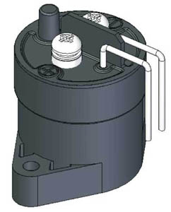
DH50 High Voltage DC Contactor

■ FEATURE
·50A Contact switch capacity, Small volume;
·A set of bridge type N.O.contacts contact circuit has "+", "-" polarity;
·Application:Telecom equipment、Solar system、 Engineering machinery、Electromobile、Electric vehicle、Charging system、Train、Ships、UPS etc.;
·Safety Approvals:CCC
·Comply with the ROHS
■ SPECIFICATION
|
Product No.
|
DH50C□ANA
|
|
Contact type
|
1H (SPST-NO)
|
|
Contact material
|
Cu Alloy
|
|
Rated load current of contact(Resistive load)
|
50A×450V DC (DC-1)
|
|
Contact voltage drop
|
50A@max.80mV
|
|
Insulation resistance
|
Min. 100MΩ @ 500VDC
|
|
Dielectric strength
(Between Insulated Electric Parts)
|
2200VAC 50 Hz/60 Hz (1 minute)
|
|
Pick-up time
|
Max. 20ms.
|
|
Release time
|
Max. 10ms.
|
|
Operating ambient temperature
|
-40℃~+85℃
|
|
Storage ambient temperature
|
-55℃~+120℃
|
|
Relative humidity
|
20%~90% RH
|
|
Vibration(Sinusoid、80~2000HZ、peak)
|
(80~2000)HZ,≤20g
|
|
Shock(11ms,1/2 Sinusoid、peak、pick-up)
|
≤20g
|
|
Mechanical life
|
300,000times
|
|
Electrical life
|
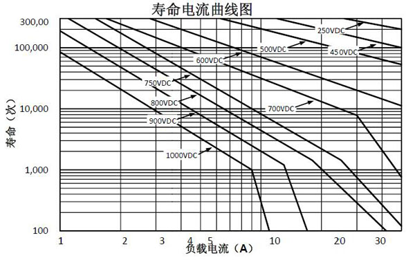
Please refer to diagram of resistance load life
|
|
Pollution level
|
Ⅲ
|
|
Working duty
|
Continuous
|
■ COIL DATA
|
P/N
|
Coil voltage(V)
|
Coil operating voltage(V)
|
Pick-up voltage(V)
|
Release voltage(V)
|
Maintain current(A)
|
Coil power(W)
|
|
DH50C□ANA
|
12
|
0.85US~1.1US
|
9V max
|
0.6V~3.6V
|
0.33
|
3.9W
|
|
24
|
18V max
|
1.2V~7.2V
|
0.17
|
4W
|
|
48
|
36V max
|
2.4V~14.2V
|
0.09
|
3.9W
|
■ Resistive load life at different voltages
■ PRODUCT MODEL DEFINE
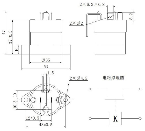
■ Outline mounting dimension and circuit diagram
▇ PRODUCT USE INSTRUCTIONS
1、 The rated electrical life is based on resistance load test. The load max inductance≤300μH; If used with inductive load, please do contact the factory first.
2、 The above curve is drawn according to the test and infer data. Suggest users confirm in practical use.
3、 When the product’s Dielectric withstand voltage、insulation resistance is less than the product parameters in the table, the product is defined as a life to an end.
4、 Product max pick-up current is 250A to avoid contact cold welding.
5、Do use washer when installing the contactor in case the screw fall off. Refer to the following specified range of tighten screw torque, the products may be broken if exceed beyond the maximum torque:
The torque of contact(M5 nut):1.2N.m
The torque of installing:2.3 N.m
6、The coil is polarized, it should be wired according to the product mark;
7、Do not use the product which have been dropped off.
8、Avoid to install the products in strong magnetic field (near the transformer or magnet), or close to the thermal radiation of the objects.
9、Electrical life
This contactor is a kind of high-voltage DC switch; it might be lost the function of cutting off in its final breakdown mode. Therefore, do not use in the condition of exceeding its’ switching capacity and life parameters (please treat it as a product with a specified life and need to be replaced if necessary). Once the contactor loose the function of disconnect and cutting, it could cause the burning of surrounding parts, so it should have a good design of circuit diagram, ensure the power supply can be cut off in 1 second.
10、The diffusion life of internal gases
This contactor designed with gas-tight silo contact point, there is gas in the silo, the diffusion life of gas is decided by the silo temperature(that is Environment Temperature + Temperature rising of the contact electrical), therefore, please make sure the environment temperature should be between -40℃ and +85℃.
11、If the contactor’s coil and contact point is energized continuously with rated voltage (or current),the power is cut off and turned on immediately, at this time due to the coil temperature increases, the resistance of the coil will increase too, so as to cause the pick-up voltage increased, it may cause beyond the rated pick-up voltage , in this case, please take following measures, such as: Reduce the load current, limited duration electricity or Use the higher coil voltage than the rated pick-up voltage.
12、The main contact rated parameters is available at resistance load, if use inductive load (L load) and at the same time the L/R > 1 ms, it should be paralleled a surge current protection device for the inductive load.
13、Product coil drive circuit of power must be larger than the product coil power, otherwise it will reduce the product’s cutting ability.
14、Be careful not to let the debris or oil pollute the main terminal, and the lead-out wire terminal should be reliable contact with the main terminal, or the terminal would be highly heated. At the same time, the lead wire which connected to the product must achieve its conductive capability, to prevent overheating and impact the electrical life.


