
 CN
CN EN
EN ES
ES RU
RU FR
FR AR
AR
Contact Us for All Your Needs
Our professional team will be online to provide you with the most suitable products for you.


When an electric vehicle fails to start, a charging station refuses to deliver power, or a renewable energy inverter stops feeding the grid, the root cause is often traced to a component that is hidden inside a sealed enclosure: the DC power switching device that connects and disconnects the high‑current circuit. A failing DC Contactor rarely stops working without warning. It sends signals—audible, visible, and measurable—that indicate a problem is developing. Recognising these signals early can prevent an unplanned shutdown, a stranded vehicle, or a damaged battery bank.
The diagnostic steps below apply to electromagnetic DC switching components commonly used in electric vehicles, industrial equipment, telecom power supplies, and renewable energy systems. They cover the four failure modes that field technicians encounter most frequently.
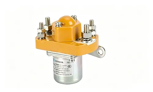
When the control circuit sends a signal to the coil but the main contacts do not close, the first check is the coil circuit itself. Measure the voltage at the coil terminals while the close signal is active. The measured voltage must be within the coil's rated operating range—typically ±10% of the nominal value. A 12 V coil that receives only 9 V may not generate enough magnetic force to pull the armature. A 24 V coil that receives 28 V during battery charging is within tolerance; the same coil at 32 V is not and may have already suffered insulation damage.
If the voltage is correct, de‑energise the circuit and measure the coil resistance. Compare the reading to the manufacturer's specification. An open circuit indicates a burnt‑out coil winding. A reading significantly lower than the specification suggests shorted turns, which reduce the magnetic field and can prevent closure. For coils with integrated suppression diodes, ensure the multimeter leads are connected with the correct polarity; a reverse‑biased diode will show an open circuit in one direction, which is normal.
Coil burnout is often caused by overvoltage, a failed suppression diode that allowed excessive back‑EMF, or an environmental condition that exceeded the coil's insulation rating. If the coil is burnt, replacing only the coil may solve the immediate problem, but the root cause—the overvoltage or the missing diode—must also be corrected.
A contactor that stays closed after the coil is de‑energised is a serious safety hazard. The most common cause is welded contacts. When the contacts open under load, an arc forms between them. If the load current exceeds the contactor's rated breaking capacity, or if the arc is not extinguished quickly enough, the heat can melt the contact material. When the contacts cool, they fuse together.
Welding is more common in DC circuits than AC circuits because the DC arc does not self‑extinguish at a zero‑crossing point. The arc must be stretched and cooled by the contactor's magnetic blowout design or arc chute. A contactor that has welded once is permanently damaged. Even if the contacts are separated manually, their surfaces are rough and will weld again at a lower current.
To test for welded contacts, de‑energise the coil and measure continuity across the main terminals. If the circuit is closed when the coil is off, the contacts are welded. The contactor must be replaced.
A less severe cause of failure to open is residual magnetism in the iron core. This occurs when the core material retains a small magnetic field after the coil is de‑energised. The spring mechanism is designed to overcome this residual force, but if the spring has weakened or the core has been overheated, the contacts may delay opening or fail to open. A delayed opening produces a prolonged arc that accelerates contact wear.
Chattering—rapid opening and closing of the contacts—is usually caused by an unstable coil voltage. If the control circuit has a loose connection, a failing DC‑DC converter, or a corroded terminal, the voltage at the coil may fluctuate around the minimum pull‑in voltage. The contactor closes when the voltage rises, opens when it drops, and cycles rapidly in between.
Chattering destroys the contacts. Each unintended opening draws an arc, and the cumulative damage can weld the contacts or erode them to the point where they no longer make reliable contact. The fix is to stabilise the coil voltage. Check all connections in the control circuit, verify the output of the power supply, and ensure that the wiring is adequately sized for the coil current.
A loud hum in a DC switching device is less common than in an AC unit, because DC coils do not experience the alternating magnetic field that causes 50 Hz or 60 Hz hum. However, a DC coil can hum if it is being driven by a pulse‑width‑modulated (PWM) signal rather than a steady DC voltage. The PWM frequency may be within the audible range. Specifying a coil rated for PWM operation, or adding filtering to the PWM output, resolves this.
Physical inspection can reveal problems that electrical measurements miss. Disconnect the power and examine the contactor for:
Discoloured terminals. Blue or brown discolouration of the main terminals indicates that the contact resistance is too high and the terminal has been running hot. The cause may be loose connections, corrosion on the busbar mating surface, or internal contact wear.
Arc marks or carbon tracking on the housing. If the arc has escaped the arc chute and deposited carbon on the contactor housing or adjacent components, the arc‑extinguishing mechanism is not functioning correctly. This can occur if the contactor is operated above its rated breaking current or if the arc chute is damaged.
Corrosion on the coil terminals or the iron core. In marine, coastal, or high‑humidity environments, moisture ingress can corrode the coil terminals or the core, leading to high coil resistance or mechanical binding.
If any of these signs are present, the contactor should be replaced. However, the installation environment should also be assessed. A contactor that has corroded in service may need to be specified with a higher environmental rating or protected by a sealed enclosure.
When a DC switching device is suspected of failing, the following sequence will identify the root cause in most cases:
Visually inspect for discolouration, arc marks, corrosion, or mechanical damage.
Measure the coil voltage during operation and compare to the coil's rated range.
Measure the coil resistance (power off) and compare to specification.
Check for welded contacts by verifying open‑circuit condition with the coil de‑energised.
Inspect the control circuit for loose connections, a failing power supply, or a missing suppression diode.
If the contactor fails any of these checks, it should be replaced with a correctly rated unit. DONGYA's range of electromagnetic DC switching devices includes models from 50 A to 600 A with coil voltages of 12 V, 24 V, and 48 V, covering the most common ratings found in electric vehicles, industrial equipment, and renewable energy systems.
The most effective way to diagnose a failing contactor is to detect the problem before it fails. A monthly inspection that includes a visual check for discolouration and a measurement of coil resistance will catch most developing faults. The inspection should be logged, and any trend—such as a gradually increasing coil resistance—should trigger a planned replacement during scheduled maintenance rather than an emergency repair after a failure. For a full range of DC switching components designed for reliable long‑term operation, selecting the correct current rating and coil voltage from the start reduces the likelihood of premature failure.
A DC power switching device is a predictable wear item when it is operated within its ratings. When it is pushed beyond those ratings—by overvoltage, excessive current, or a harsh environment—it becomes an unpredictable failure point. The diagnostic approach above provides a structured way to identify which of those conditions is causing the problem and to correct it before the next contactor is installed.
GET A QUOTE