
Contact Us for All Your Needs
Our professional team will be online to provide you with the most suitable products for you.

2.1 Standards: IEC 60947, GB 14048.2, UL489A, UL1077
2.2 Rated working voltage Ue: DC80V,DC125V; AC120/240V; AC240V; AC277/480V
2.3 Mechanical/Electrical endurance: 10000/6000,(UL489A approved at electrical endurance: 1000)
2.4 Dielectric strength: the main circuit: 3000V, the auxiliary circuit: 1000V
2.5 Certificates: CCC, CE, TUV, VDE,UL1077, UL489A,UL489
2.6 Auxiliary contact: AC250V 5A
2.7 Rated breaking capacity Icn:
Application
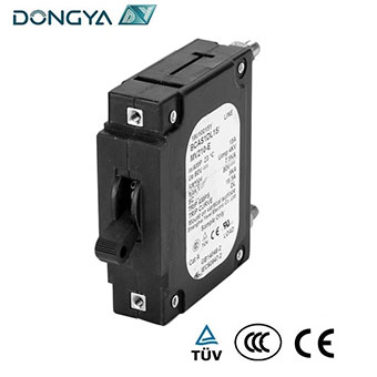
BC series circuit breaker for equipment (hydraulic-magnetic circuit breaker) is used in the power system with rated current up to DC400A and AC100A, rated voltage up to AC277/480V (50/60Hz) or DC125V. It provides overload, short circuit protection. It can also be used for infrequent close or open. The application fields are computer and peripheral equipment, industrial automatic control system, telecom equipment, power supply system, UPS, railroad, marine, spacecraft, elevator, portable power supply and so on.
Specification
|
Rated voltage (V) |
Rated current (A) |
Number of poles |
Breaking capacity (A) |
||||
|
TUV, CE, CCC |
UL1077 |
UL489A |
UL489 |
||||
|
Ics |
Icu |
||||||
|
DC80V |
0.5-100 |
1,2,3 |
7500 |
7500 |
50000 |
50000 |
50000 |
|
DC80V |
50-200 |
2P parrallel |
7500 |
10000 |
50000 |
50000 |
/ |
|
DC80V |
150-300 |
3P parrallel |
7500 |
10000 |
50000 |
50000 |
/ |
|
DC80V |
200-350 |
4P parrallel |
7500 |
10000 |
50000 |
50000 |
/ |
|
DC125V |
0.5-100 |
1,2,3 |
5000 |
5000 |
/ |
/ |
/ |
|
DC125V |
0.5-50 |
2,3 |
/ |
/ |
/ |
5000 |
/ |
|
AC240V |
0.5-100 |
1 |
5000 |
5000 |
/ |
/ |
/ |
|
AC277V |
0.5-100 |
2,3 |
5000 |
5000 |
/ |
/ |
/ |
|
AC240V |
0.5-30 |
1,2,3 |
/ |
/ |
5000 |
/ |
5000 |
|
AC120/ 240V |
0.5-70 |
1,2,3 |
/ |
/ |
5000 |
/ |
5000 |
|
AC277/ 480 V |
0.5-100 |
1,2,3 |
/ |
/ |
2000 |
/ |
|
2.8 Resistance:
|
CURRENT (A) |
RESISTANCE (DC) |
RESISTANCE (AC) |
CURRENT (A) |
RESISTANCE (DC) |
RESISTANCE (AC) |
|
1 |
1.38 |
1.15 |
30 |
0.003 |
0.004 |
|
5 |
0.056 |
0.052 |
50 |
0.002 |
0.004 |
|
10 |
0.018 |
0.016 |
70 |
0.0015 |
0.0014 |
|
20 |
0.007 |
0.006 |
100 |
0.00135 |
0.00115 |
|
Notes: DCR and impedance based on 100% rated current applied and stabilized a minimum of one hour |
|||||
Working condition
3.1 Altitude:≤2000m
3.2 Operation temperature:-40℃~+85℃
3.3 Humidity:≤95%
3.4 Service place without explosive media, gas and dust which are corrosive and conductive.
3.5 Be mounted free from rain and snow.;
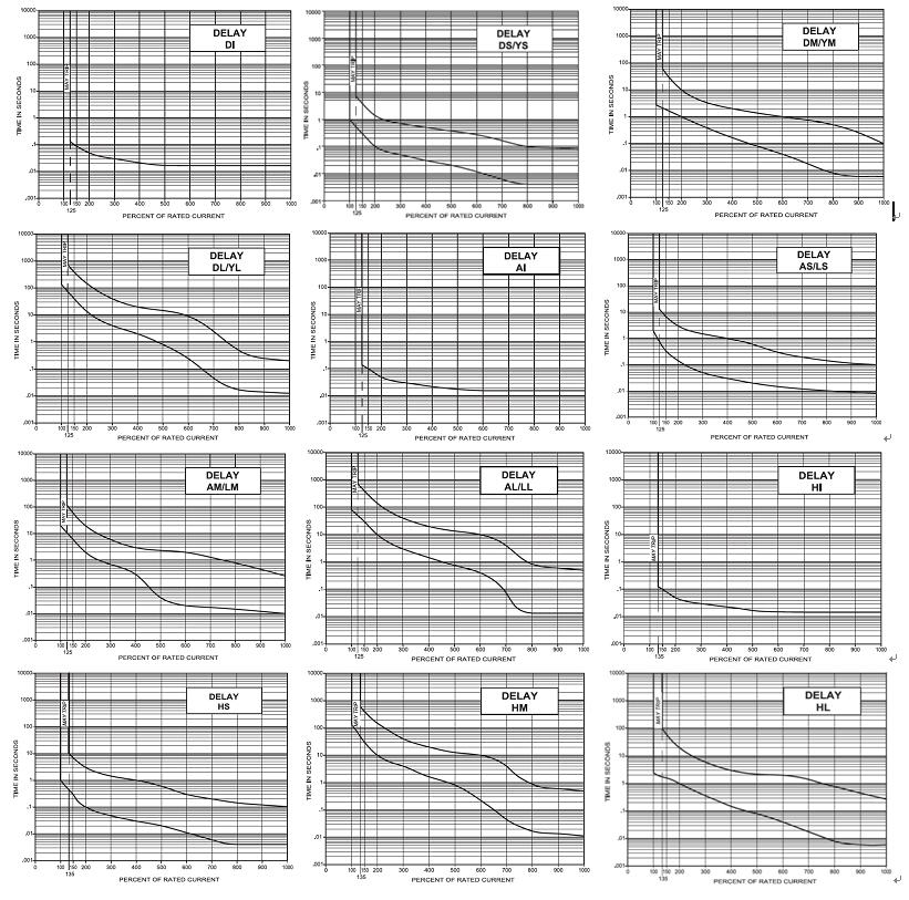
Tripping characteristic
4.1 Tripping timetable (in seconds)
|
Current Curve |
100% |
125% |
135% |
150% |
200% |
400% |
600% |
800% |
1000% |
|
DI |
No trip |
0.12max |
/ |
0.1max |
0.05max |
0.022max |
0.017max |
0.017max |
0.017max |
|
DS/YS |
No trip |
0.5~6.5 |
/ |
0.3~3 |
0.1~1.2 |
0.031~0.5 |
0.011~0.25 |
0.004~0.1 |
0.004~0.08 |
|
DM/YM |
No trip |
2~60 |
/ |
1.8~30 |
1~10 |
0.15~2 |
0.04~1 |
0.008~0.5 |
0.006~0.1 |
|
DL/YL |
No trip |
80~700 |
/ |
40~400 |
15~150 |
2~20 |
0.23~9 |
0.015~0.55 |
0.012~0.2 |
|
AI |
No trip |
0.12max |
/ |
0.1max |
0.05max |
0.022max |
0.017max |
0.017max |
0.017max |
|
AS/LS |
No trip |
0.7~12 |
/ |
0.35~7 |
0.13~3 |
0.03~1 |
0.015~0.3 |
0.01~0.15 |
0.008~0.1 |
|
AM/LM |
No trip |
10~120 |
/ |
6~60 |
2~20 |
0.2~3 |
0.02~2 |
0.015~0.8 |
0.01~0.25 |
|
AL/LL |
No trip |
50~700 |
/ |
30~400 |
10~150 |
1.5~20 |
0.4~10 |
0.013~0.85 |
0.13~0.5 |
|
HI |
No trip |
/ |
0.12max |
0.1max |
0.05max |
0.023max |
0.016max |
0.015max |
0.015max |
|
HS |
No trip |
/ |
0.44~10 |
0.3~7 |
0.1~3 |
0.03~1 |
0.012~0.3 |
0.004~0.15 |
0.004~0.1 |
|
HM |
No trip |
/ |
1.8~100 |
1.7~60 |
1~20 |
0.15~3 |
0.04~2 |
0.008~0.79 |
0.006~0.28 |
|
HL |
No trip |
/ |
50~600 |
30~400 |
10~150 |
1.8~20 |
0.22~10 |
0.018~0.88 |
0.011~0.5 |
4.2 Tripping curves

Model and Implication


|
No. |
Implication |
BC |
||||||||||||||||||||||||||||||||||||||||||||||||||||||||||||||||||||||||||||||||||||||||||
|
1 |
Product code |
B:Circuit Breaker |
||||||||||||||||||||||||||||||||||||||||||||||||||||||||||||||||||||||||||||||||||||||||||
|
2 |
Design code |
C: Type C |
||||||||||||||||||||||||||||||||||||||||||||||||||||||||||||||||||||||||||||||||||||||||||
|
3 |
Circuit |
A:Series trip (Current) V: Series trip (Voltage) T:Relay Trip S:Switch P:Parallel; |
||||||||||||||||||||||||||||||||||||||||||||||||||||||||||||||||||||||||||||||||||||||||||
|
4 |
Actuator code |
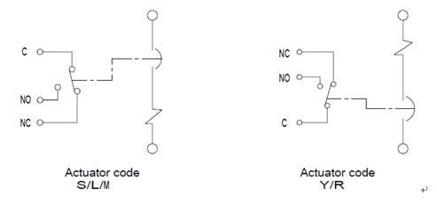
S:Long handle , One per Pole; L:Long Handle ,One per multiple unit; M: Mid Trip Handle ;Y: Rocker Handle; R:Flat Rocker Handle; D : Short Handle.; |
||||||||||||||||||||||||||||||||||||||||||||||||||||||||||||||||||||||||||||||||||||||||||
|
5 |
Number of Poles |
1, One pole ; 2,Two poles ; 3, Three poles; 4,Four poles (Parallel only.) |
||||||||||||||||||||||||||||||||||||||||||||||||||||||||||||||||||||||||||||||||||||||||||
|
6 |
Tripping curve |
DI:DC Instantaneous DS: DC Short DM: DC Medium; DL: DC Long YS: DC Short,Hi-inrush YM: DC medium, Hi-inrush YL: DC long, Hi-inrush AI: AC Instantaneous AS:AC Short AM:AC Medium; AL: AC Long LS: AC Short, Hi-inrush LM: AC Medium, Hi-inrush LL: AC Long, Hi-inrush HI: AC/DC Instantaneous HS: AC/DC Short HM: AC/DC Medium; HL: AC/DC Long |
||||||||||||||||||||||||||||||||||||||||||||||||||||||||||||||||||||||||||||||||||||||||||
|
7 |
Rated current(A) |
AC:0.5~100; DC: Series:0.5~100、Parallel:50~350(2P 200Amax,3P 300Amax,4P 350Amax) |
||||||||||||||||||||||||||||||||||||||||||||||||||||||||||||||||||||||||||||||||||||||||||
|
8 |
Mounting method |
M:M3 screw mounting; U:6-32UNC screw mounting; Q:Snap-in face plate adapter ;R: Din Rail |
||||||||||||||||||||||||||||||||||||||||||||||||||||||||||||||||||||||||||||||||||||||||||
|
9 |
Wiring method |
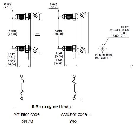
U: M6 bolt-in wiring N: 1/4-20 bolt-in wiring V: M5 bolt-in wiring (≤50A); W:10-32bolt-in wiring (≤50A) L : M5 screw wiring (≤50A) G: 10-32 screw wiring (≤50A) B: Push-in stud wiring (≤100A) C: Clip terminals (≤100A) |
||||||||||||||||||||||||||||||||||||||||||||||||||||||||||||||||||||||||||||||||||||||||||
|
10 |
Actuator & legend color |
|
||||||||||||||||||||||||||||||||||||||||||||||||||||||||||||||||||||||||||||||||||||||||||
|
11 |
Indicate Direction |
With current rating :A, Vertical; B, Horizontal; C, Indicate On Vertical Legend; D, Indicate On Horizontal Legend; E,Indicate Off Vertical Legend ;F, Indicate Off Horizontal Legend G:Indicate Off Vertical Legend with guard ; Without current rating :1, Vertical; 2,Horizontal; 3, Indicate On Vertical Legend ;4, Indicate On Horizontal Legend ; 5,Indicate Off Vertical Legend ;6, Indicate Off Horizontal Legend 7,Indicate Off Vertical Legend with guard ; |
||||||||||||||||||||||||||||||||||||||||||||||||||||||||||||||||||||||||||||||||||||||||||
|
12 |
Accessory code |
0:No accessory;1;Auxiliary Switch ;2:Trip Alarm Switch |
||||||||||||||||||||||||||||||||||||||||||||||||||||||||||||||||||||||||||||||||||||||||||
|
13 |
Certificate code |
E :CCC、 UL1077、CSA、TUV; T : CCC、 UL489A、TUV ; J: CCC、 UL489、TUV; |
||||||||||||||||||||||||||||||||||||||||||||||||||||||||||||||||||||||||||||||||||||||||||
|
14 |
Suffix code |
Identification number (Additional option) Five or more numeric digits, for different variations which is cross referenced to product ordering codes in option |
Dimensions and wiring method
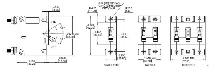
6.1 Toggle handle , Actuator code “ L”, Mounting method “ M/U”,
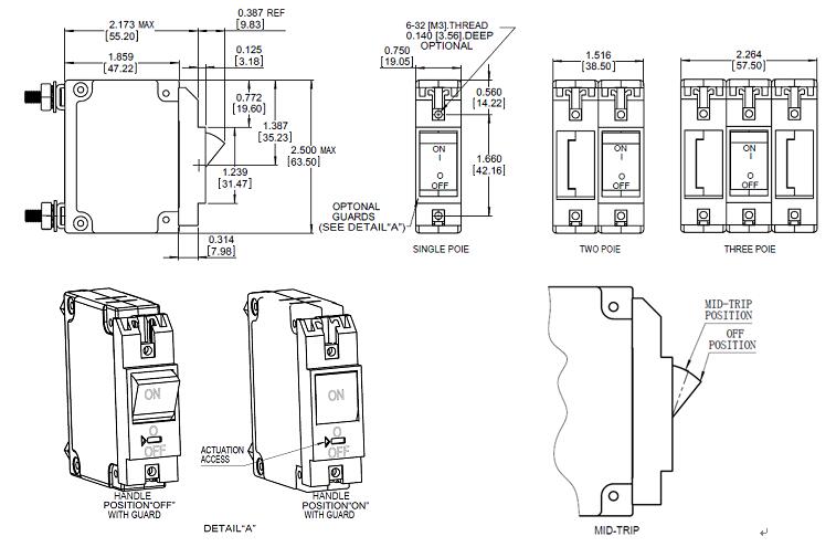
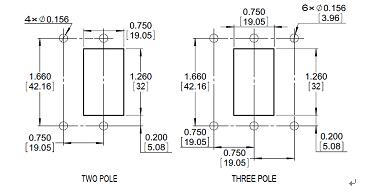
6.1.1 Outline dimensions (Tolerance ±0.02in[.51mm] Unless noted)

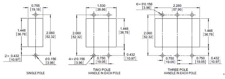
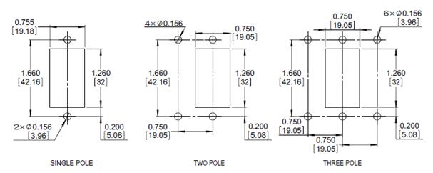
6.1.2 Mounting dimension (Tolerance ±0.005in[.13mm] Unless noted)

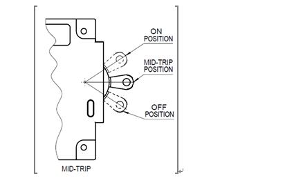
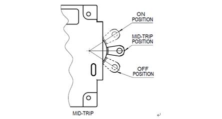
6.1.3 Toggle handle MID-TRIP

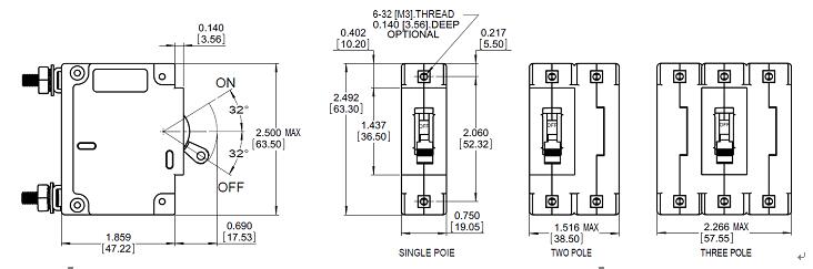
6.2 Toggle Handle,Actuator code “ S/M”, Mounting method “ M/U”,
6.2.1 Outline dimensions (Tolerance ±0.02in[.51mm] Unless noted)

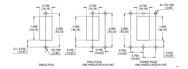
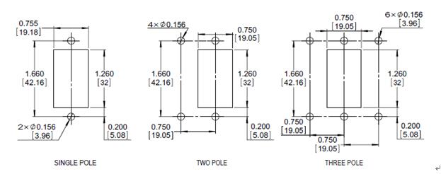
6.2.2 Mounting dimension (Tolerance ±0.005in[.13mm] Unless noted)

6.2.3 Toggle handle MID-TRIP

6. 3 Rocker Handle,Actuator code “ Y”, Mounting method “M/U”;
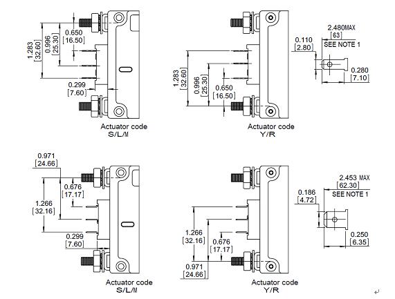
6.3.1 Outline dimensions (Tolerance ±0.02in[.51mm] Unless noted)

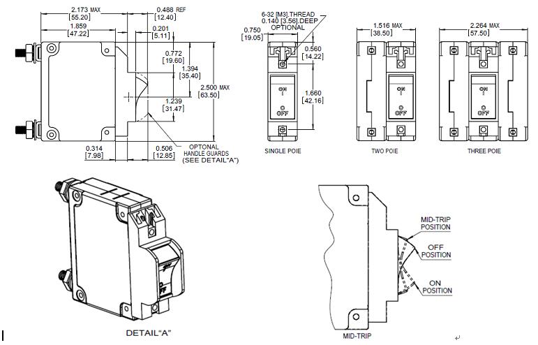
6.3.2 Mounting dimension (Tolerance ±0.005in[.13mm] Unless noted)

6. 4 Flat Rocker Handle, Actuator code “ R”, Mounting method“M/U”;
6.4.1 Outline dimensions (Tolerance ±0.02in[.51mm] Unless noted)

6.4.2 Mounting dimension (Tolerance ±0.005in[.13mm] Unless noted)

6.5 Toggle Handle, Actuator code “ L”, Mounting method “ Q”;
6.5.1 Outline dimensions (Tolerance ±0.02in[.51mm] Unless noted)

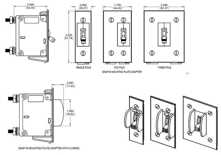
6.5.2 Mounting dimension (Tolerance ±0.005in[.13mm] Unless noted)

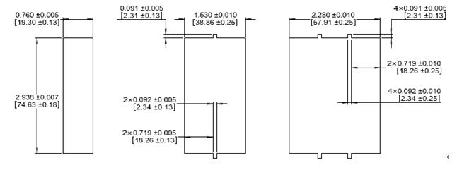
PLATE MOUNTING DEAIL
|
PANEL THICKNESS |
|
0.062±0.005 [1.57±0.13] |
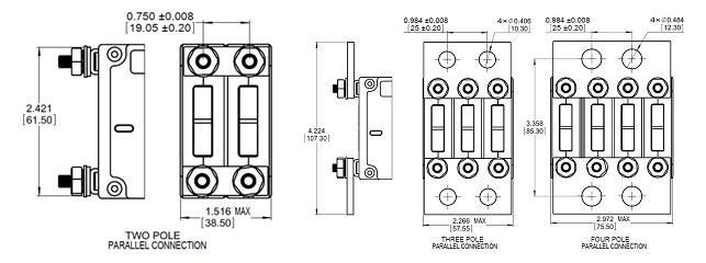
6.6 Parallel connection,Mounting method “M/U”,Wiring Method “S/K/U/N” (Actuator code “S”,2~4P;Actuator code “L/Y/R”,2~3P)
6.6.1 Outline dimensions (Tolerance ±0.02in[.51mm] Unless noted)

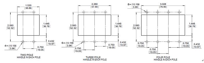
6.6.2 Mounting dimension (Tolerance ±0.005in[.13mm] Unless noted)
6.6.2.1 Actuator code “S”, Mounting method “M/U”

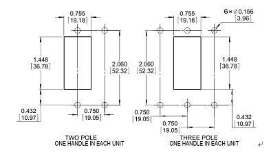
6.6.2.2 Actuator code “L”, Mounting method “M/U”

6.6.2.3 Actuator code “R/Y”, Mounting method “M/U”

Auxiliary and Alarm Switch
7.1 Outline dimensions (Tolerance ±0.02in[.51mm] Unless noted)

7.2 Auxiliary Switch Circuit diagram

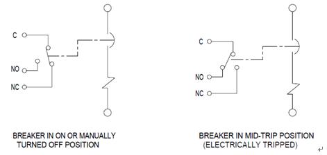
7.3 Alarm Switch Circuit diagram

NOTE:
1 :Dimensions That Reference This Note Are Taken From Back of Mounting Panel.
Wiring method and dimension (Tolerance ±0.031in[0.8mm] Unless noted)

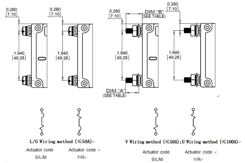

|
M6 |
0.510[12.95] |
0.652[16.56] |
|
1/4-20 |
0.545[13.84] |
0.687[17.45] |
|
M5 |
0.510[12.95] |
0.625[16.56] |
|
10-32 |
0.545[13.84] |
0.687[17.45] |
|
SCREW SIUD THREAD |
DIM“A” ±0.045[1.14] |
DIM“B” ±0.035[0.89] |
Note:During wiring, applied torque on each type screw is shown in following table
|
Diameter of screw (mm) |
Applied torque (N.m) |
|
M3(6-32) Mounting Screw |
0.5 |
|
M6(1/4-20)Bolt-in |
3.0 |
|
M5(10-32) Bolt-in |
2.0 |
|
M5(10-32)Screw |
2.0 |
|
M6(1/4-20)Bolt-in Parallel |
5.0 |
Packing and depositing
The products should be stored in the warehouse where there are ventilation. The relative humidity there should not exceed 80%, and the ambient temperature there is between -25℃ to +60℃. In addition, there should not be acidic, alkaline and corrosive gas in the air. The products should not be deposited more than 3 years in the above mentioned conditions since the producing date.
Notice
10.1 Do not disassemble the breaker privately.
10.2 Attention to live part when the breaker is energized and avoid touching them.
10.3 Please make sure reliable connection to avoid fault tripping or damage of terminal caused by exceptional heat resulting from unsuitable connection.
10.4 Please maintain the distance of 45mm from the arc jet slot of the product (LINE side) when installation in case there is short circuit breaker due to arc jet.
10.5 The breaker should be mounted within 5° of the mounting plane in case the characters of the product are affected.
10.6 The fasten torque of screw is 0.5N.m.。
GET A QUOTE