Contact Us for All Your Needs
Our professional team will be online to provide you with the most suitable products for you.

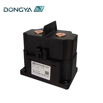
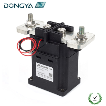
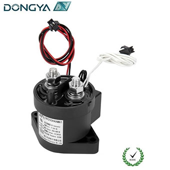
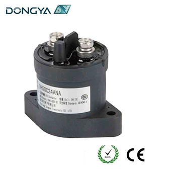
DC contactors are indispensable in DC-powered systems—from solar energy storage to electric vehicle (EV) powertrains and industrial motor controls. Unlike AC contactors, they operate in circuits with unidirectional current and no natural zero-crossing, making arc management and parameter matching far more critical. Poor selection can lead to contact ablation, equipment downtime, or even safety hazards like short circuits. Below are the non-negotiable precautions to follow.
The main contacts of a DC contactor bear the full voltage of the circuit, so their rated voltage must never be lower than the load’s maximum operating voltage. This is non-negotiable for two key reasons:First, DC current has no zero-crossing, meaning voltage stress on contacts is continuous. If the contact’s rated voltage is insufficient, dielectric breakdown (insulation failure) can occur between separated contacts—triggering sparks, short circuits, or permanent damage to the contactor’s insulation layer.Second, DC circuits with inductive loads (e.g., motors, transformers) often generate transient voltage spikes when the contactor disconnects. These spikes can be 2–3 times the nominal load voltage. To account for this, select a contactor with a main contact rated voltage that exceeds the load’s nominal voltage by 10–20% (not just "equal to" it). For example, a 48V DC motor load should pair with a contactor rated for at least 55V, not just 48V.
DC circuits, especially those with inductive loads, experience significant inrush currents during startup. When a motor or inductor powers on, the magnetic field builds rapidly, causing current to surge beyond the load’s steady-state rated current (typically 1.2–1.5 times higher). If the contactor’s main contact rated current only matches the load’s nominal current, this inrush can overheat contacts, accelerate wear, or even weld contacts together (a fatal failure for circuit control).
The industry standard is to select a contactor with a main contact rated current of at least 1.3 times the load’s rated current. For high-inrush applications (e.g., EV traction motors), increase this buffer to 1.5 times. Additionally, consider the contact material: silver-cadmium oxide or silver-tin oxide contacts handle high currents and arcing better than pure silver, making them ideal for heavy-duty loads.
The contactor’s coil—responsible for activating the electromagnetic core—relies on a separate control voltage. Choosing the right coil voltage is not just about compatibility; it’s about safety and system reliability:
•Simple, low-risk circuits: For standalone equipment (e.g., small DC pumps) with few electrical components and minimal human interaction, 220V or 380V AC coils (or equivalent DC coils) work well. They simplify wiring and reduce the need for additional transformers.
•Complex or safety-critical circuits: In factories, EV charging stations, or areas with frequent maintenance (where technicians may interact with wiring), opt for low-voltage coils (36V, 110V, or 127V DC/AC). These voltages comply with safety standards (e.g., IEC 61200 for low-voltage protection) and minimize electric shock risk.
Also, verify that the coil voltage tolerates fluctuations. A coil rated for 110V should operate reliably between 85–110% of its rated voltage; voltages outside this range can cause weak magnetic force (leading to contact chatter) or coil burnout.
DC contactors have two types of contacts: main contacts (for power circuits) and auxiliary contacts (for control circuits, e.g., signaling, interlocking, or feedback). Overlooking auxiliary contacts is a common mistake that can render the control system non-functional.
•Quantity: Count how many "on/off" signals or interlocks the system needs. For example, a motor with "start-stop" and overload protection may require 1 normally open (NO) auxiliary contact (for start latching) and 1 normally closed (NC) auxiliary contact (for overload shutdown).
•Type: NO contacts close when the contactor is energized; NC contacts open. Ensure the mix matches your logic—e.g., a battery storage system may need NC auxiliary contacts to trigger an alarm if the contactor fails to energize.
For high-frequency control signals, select auxiliary contacts with silver-nickel plating to resist wear from frequent switching.
Operating frequency (number of on/off cycles per hour) directly impacts contact life. Each time contacts open, an arc forms; frequent arcing heats contacts, erodes their surface, and increases the risk of welding.
If the system’s switching frequency exceeds the contactor’s rated value (typically 600–1,200 cycles/hour for standard models), upgrade to a contactor with a one-level higher rated current. For example, a 50A contactor rated for 600 cycles/hour may fail in a 1,000-cycle/hour application—switch to a 63A contactor instead.
High-frequency applications may require "high-performance" DC contactors with enhanced arc-extinguishing chutes and heat-resistant contact materials.
Selecting a DC contactor is a balance of technical precision and application awareness—skipping any of these precautions can lead to costly failures. If you’re unsure about calculating inrush current, matching contact types, or choosing between standard and high-performance models, consult DONGYA we will provide you with a suitable solution.
[AI-Generated Content Marker: This article was led by human industrial electrical expertise (≥70%), with AI assisting in structuring technical details and refining language clarity.]
GET A QUOTE